Project: Marta
Rail Maintenance Facility, Atlanta, GA
Prime Contractor:
Archer Western
Scope: 1100+
feet of 60” ID Weholite
(by KWH Pipe) polyethylene drain piping with internal
extrusion welded joints.
Pipe Supplier:
Allstar Pipe & Supply; Mark McDonald, Sales
Reference: Shaffer & Associates; Ron Shaffer, President
Welding:
Plastifab, Inc.
One of the many things
I have learned over the years is that no matter how well you prepare
for a job there will always be unforeseen events that will challenge
you. Some will be costly and some will offer a chance to discover new
limits.
Such was the case in
the above-mentioned project. While I had been doing extrusion welding
for better than 15 years, I had never had the problems and
opportunities afforded me on this project. First, I was given almost
six months to prepare for the job. Since better than 50% of our
business is service related, we are well acclimated to emergency
calls of little notice. That lead-time made this project seem like a
godsend!
Given that rare
opportunity, I had time to imagine all the pain involved in extrusion
welding 60” joints internally. The hybrid extrusion welder we
use weighs in at 25 pounds and seemingly increases in weigh
proportionally to the amount of time it is suspended over your head.
Past experience in joining of pipe by extrusion welding also allowed
me the knowledge that alignment of pipe wall was always a problem.
Combining those two issues was enough to put my mind to work on
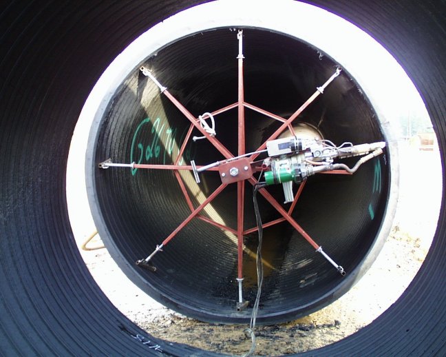
designing a jig (Illustration 1) that would both allow for alignment
and support of the extrusion welder. Conception to completion took
some 60 to 70 hours of design and building time. Armed with that jig
and other necessary equipment, I set out to perform my contracted
portion of the project.
Illustration 1
Once set up with the
pipe installation crew the goal was completion of 2 joints per day of
the 50-foot lengths of pipe. The pipe was to be laid on grade in
trench and welded in place. This scenario presented some particular
problems in the fact that the pipe had to be shifted around on both
axis to allow for closure of the joints to proper tolerances per the
manufacturer’s specs for welding. Add to that the thermal
expansion in the pipe wall from the sunlight that made the joint seem
like a moving target and each resultant joint developed its own
“personality.”
At the end of the first
three days we had 250 foot of pipe completed. Of that, 150 foot was
buried in #57 stone and 24” of compacted sand over. Having a
weekend break at this point we discussed leaving an excavator bucket
resting on the end of the pipe in case of rain but decided against it
for fear of damage to the pipe due to bleed off of the boom. That was
a Friday afternoon and we were to return on Monday.
A portion of the
learning curve kicked in when Mother Nature decided to drop about 4”
of rain that Saturday. The area we were working was one of the runoff
areas for I-75/I-85 corridor of downtown Atlanta. It would be hard to
imagine just how much surface runoff passed through the area. But, it
was enough to rip apart one of the welds and float 200 foot of the
250 foot of pipe that was in place in the trench (Illustration 2). The fill
that had been around the pipe then washed into the remaining piece of
pipe and everything downstream from there.
Illustration 2
After
initially surveying the damage with the contractor Monday morning I
was asked just how much stress the extrusion welds in the pipe would
take. I had but one answer and that was, “I guess we are about
to find out!” It was fortunate that the job was large enough
that there was additional equipment onsite to be used. By mid-morning
we had assembled enough machinery to lift the 200-foot section
(approximately 12,200 lbs.) from the trench and up onto the ground
above. The lift
was made from 4 points in the line and done with the minimum amount
of movement. The pick points were selected so as to minimize the
stress created on the remaining joints (Illustration 3). Once the pipe
cleared the surface it was moved back from the trench so as to free
up the necessary work area for the trench to be cleaned and returned
to the proper grade. By early afternoon the pipe was ready
to be reset in the trench. It was aligned with the section that had
remained in place and welded again before day’s end.
Illustration 3
It was amazing how
quickly everybody’s mind went to work the next morning based on
the experiences of the preceding day. A short onsite meeting with the
pipe crew, construction managers, engineering personnel and myself
resulted in a complete change of planning for the rest of the piping
project. It was determined that the pipe could be welded into 150
foot sections off to the side of the trench and then set in place
without damaging the welds. The 150-foot lengths were considered to
be logistically the best length for construction and placement. This
allowed the pipe crew to open and prepare trench while we were left
to weld the joints well out of their area of operation.
The balance of the job
was pretty much boilerplate with the exception of buried obstructions
causing some unforeseen delays. By that time all of the crew had
become comfortable with what could an couldn’t be done with the
extrusion-welded pipe, although everyone wanted to know just how much
stress the extrusion welds were capable of withstanding. While I was
busy inside welding one of the sections in place in the trench the
crew decided it was time to test the welds “to the extreme!”
That arbitrary decision presented the most valuable experience in the
entire scope of the project.
I had advised the trenching foreman to use a nylon choker to drag the
standard 150-foot welded sections from the prep area to trench side
for placement. The crew, knowing we were near completion, was not to
be denied the opportunity to satisfy their curiosity. I emerged to
find them, having picked a 100 ft. section with two chokers rigged
approximately three feet out from each side of the weld, transporting
said section completely elevated (Illustration 4). Although my initial
reaction was to immediately stop them, the combination of my own
curiosity and the fact that they were already under way caused me to
rethink the situation.
Illustration 4
The preparation area had been leveled to the best of the contractor’s
ability but the excavator being used for the transport was creating a
goodly amount of flex in the sections as it was moving across the
lot. The two 50 foot pipe sections weighed in at 3050 pounds each
and, to my way of thinking, were creating an untold amount of stress
on the weld. But, in the end, the pipe made it to trench side with
the weld intact.
Since the project’s
completion I have queried a number of my “engineering-type”
friends as to how to calculate the amount of stress and strain placed
on the joint during that trek across the jobsite. No one could offer
a “proof positive” formula. It probably wouldn’t
matter because now that we have tested one extrusion-welded joint no
one will be satisfied until the opportunity presents itself to test a
section with multiple joints to the breaking point. That opportunity
is highly unlikely since we can hardly expect a contractor to be the
guinea pig for a type of polyethylene welding still sometimes
referred to as “an art form.” But that doesn’t
mean that we can’t keep learning on the go!